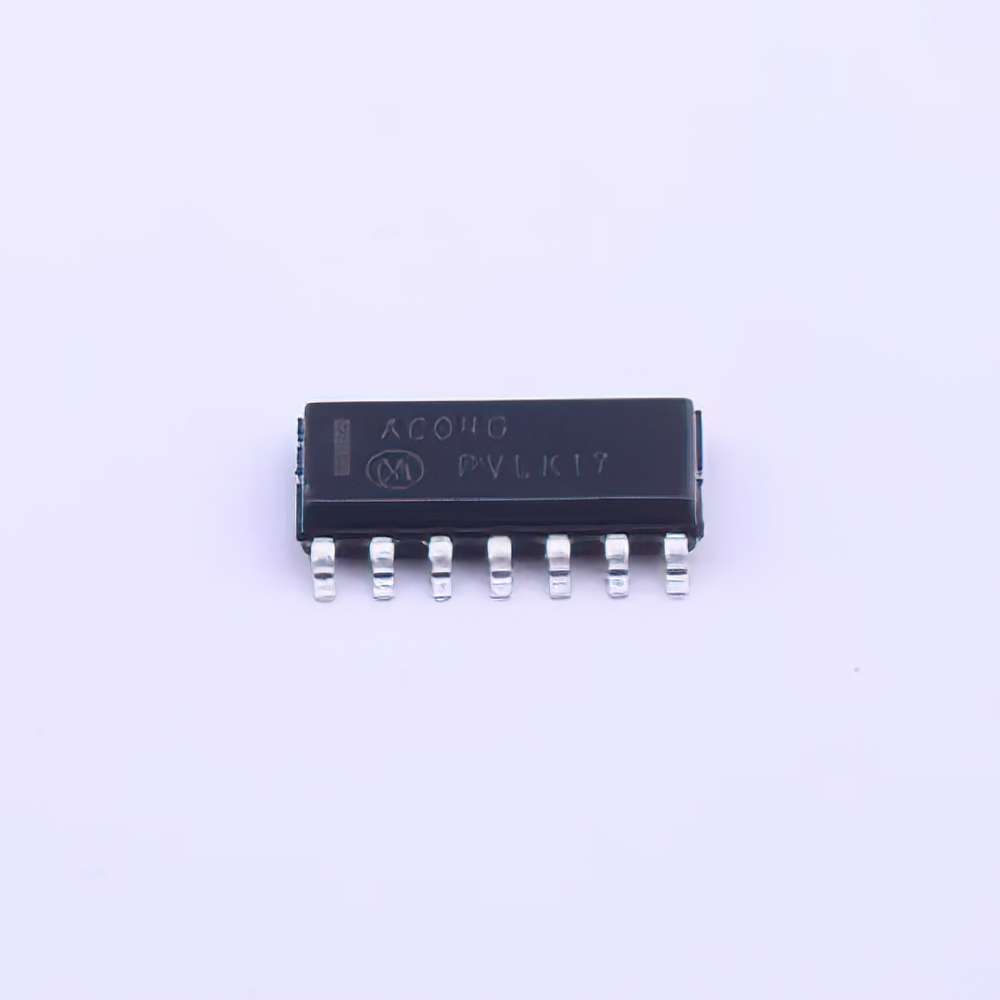
Common Troubleshooting Scenarios for MC74AC04DR2G
The MC74AC04DR2G is a widely used hex inverting IC in digital circuits. It’s part of the 74AC series and is often chosen for its high-speed operation, low Power consumption, and reliability. However, like all components, it can sometimes encounter issues during operation, which can result in malfunctioning circuits or unexpected behavior. Understanding the potential problems and knowing how to address them can save time and ensure a smooth development process.
1.1 Problem: Incorrect Output Signal Levels
One of the most common issues faced with the MC74AC04DR2G is incorrect output signal levels. When the device is powered, users may find that the output signal is either too high or too low compared to the expected logic levels. This can occur for several reasons:
Inadequate Power Supply: The MC74AC04DR2G requires a stable power supply (typically 5V). If the voltage is fluctuating or is lower than the required level, it can cause abnormal behavior.
Improper Input Conditions: If the input signals fed into the IC are noisy or not within the expected logic voltage levels (typically 0 to 5V for standard TTL logic), the IC may fail to operate as intended, resulting in incorrect outputs.
Solution:
Check the power supply: Ensure the voltage supplied to the IC is within specifications (typically 5V, with a tolerance of ±10%). Use a multimeter or oscilloscope to verify the voltage stability at the Vcc pin.
Verify input logic levels: Use a logic analyzer to check that input signals are within the appropriate voltage range. Inputs should be high (above 2V) or low (below 0.8V) for reliable logic state recognition.
1.2 Problem: Oscillations and Noise on the Output
Another common issue with the MC74AC04DR2G, particularly in high-speed circuits, is unwanted oscillations or noise on the output signal. This is often observed when the IC is used in environments with significant electromagnetic interference ( EMI ) or poor signal integrity.
Unterminated Inputs: If any of the inputs of the IC are left floating (not connected to either a high or low voltage), it can lead to oscillations or erratic behavior. This is because floating inputs can pick up noise, causing unpredictable output signals.
Poor PCB Layout: A poorly designed printed circuit board (PCB) can exacerbate noise issues. If the traces are too long or if the IC is placed near high-current paths, it can induce unwanted noise in the circuit.
Solution:
Properly terminate all inputs: Ensure that all inputs to the IC are either tied to a logic high or low voltage using resistors or driven by a proper source. Floating inputs can cause the IC to malfunction, leading to erratic outputs.
Improve PCB layout: Ensure that the IC is placed away from noisy components or high-current traces. Use ground planes and ensure that signal traces are as short as possible. For high-speed circuits, use decoupling capacitor s close to the power pins to filter out noise and stabilize the supply voltage.
1.3 Problem: IC Overheating
Another issue that users may face is the overheating of the MC74AC04DR2G. This is often caused by excessive current draw or inadequate heat dissipation.
Excessive Current: If the IC is driving too many loads or if the output pins are directly connected to heavy current consumers without proper resistive limiting, it could overheat.
Inadequate Cooling: In high-density designs or when the IC is part of a larger system, insufficient heat dissipation can lead to the IC becoming too hot to function properly.
Solution:
Limit current draw: Ensure that the IC’s outputs are not overloaded. If necessary, use series resistors or buffer stages to drive heavy loads.
Improve ventilation and heat dissipation: Ensure adequate airflow in the device, especially in enclosed or high-density systems. Using heat sinks or spreading out the components can help manage the thermal load. Monitor the temperature of the IC during operation to ensure it does not exceed the maximum rated operating temperature.
Advanced Troubleshooting Tips and Preventative Measures
While the common issues discussed in Part 1 can often be resolved with basic steps, more complex problems may require advanced troubleshooting techniques and preventative measures to ensure the long-term reliability of the MC74AC04DR2G in your circuit.
2.1 Problem: Faulty Logic Behavior due to Incorrect Timing
In digital circuits, timing is crucial, and issues related to signal timing can cause the MC74AC04DR2G to produce incorrect outputs. If the setup or hold times for the inputs are violated or if the IC is subjected to glitches in the Clock signal, it can lead to faulty logic behavior.
Clock Glitches: If the IC is part of a sequential logic circuit, glitches in the clock signal or other asynchronous input signals can result in incorrect or unpredictable output behavior.
Setup and Hold Time Violations: Each digital logic gate has specific setup and hold time requirements for its inputs. Violating these constraints can cause incorrect or delayed outputs, leading to instability in your system.
Solution:
Use proper clock debouncing techniques: Ensure that any clock signals fed into the IC are debounced properly. Use low-pass filters or Schmitt triggers to clean up noisy clock signals.
Ensure adequate timing margins: Check the setup and hold times for the inputs relative to the clock signal. Use simulation software to model the timing characteristics of your circuit and ensure that all timing constraints are met.
2.2 Problem: Incorrect Behavior in High-Speed Circuits
When the MC74AC04DR2G is used in high-speed digital circuits, issues like signal integrity and propagation delay become more critical.
Signal Integrity Issues: High-frequency signals can degrade as they travel through the PCB traces, leading to reflections and signal degradation. This can cause the IC to misinterpret the signals, resulting in incorrect logic levels or signal timing errors.
Propagation Delays: The MC74AC04DR2G is designed for high-speed operation, but excessive trace length or improper termination can add unwanted propagation delay, disrupting the timing of the circuit.
Solution:
Minimize trace lengths: Keep the signal traces as short as possible, especially for high-speed signals. Use controlled impedance traces for critical signals to ensure proper signal integrity.
Use termination resistors: Implement series termination resistors or other impedance-matching techniques to prevent reflections and improve signal integrity. This is particularly important in high-frequency applications.
2.3 Preventative Measures to Avoid Future Issues
In addition to troubleshooting existing problems, implementing preventative measures can help avoid issues with the MC74AC04DR2G in the first place. Here are a few suggestions:
Use Decoupling Capacitors : Place decoupling capacitors as close as possible to the Vcc and GND pins of the IC. These capacitors help filter out noise from the power supply and provide local energy storage to the IC.
Avoid Overloading the IC: Never exceed the recommended load driving capability of the IC. If necessary, buffer the outputs to drive larger loads.
Choose Quality Components: Always choose components that meet the specifications outlined in the datasheet. Using subpar or mismatched components can lead to operational failures.
2.4 Conclusion
The MC74AC04DR2G is a reliable and robust component when used correctly in digital circuits. However, as with any electronic component, issues can arise during operation. By understanding the potential problems and applying the troubleshooting techniques and solutions discussed in this article, users can ensure smooth performance and longevity for their circuits. Regular maintenance, careful design practices, and attention to power supply and signal integrity can minimize the risk of encountering issues with this versatile IC.
Partnering with an electronic components supplier sets your team up for success, ensuring the design, production, and procurement processes are quality and error-free.


